The Borborema Province and its gigant shear zone networks

The NE “corner” of South America, known among geologists as the Borborema province, is penetrated by beautiful transcurrent shear zone networks, with the largest ones being several tens of kilometers wide and extending for hundreds of kilometers, now limited by the Atlantic Ocean in the east and the Phanerozoic Parnaiba Basin in the west. They continue under the Parnaiba basin to form the Transbrasiliano lineament, and to the NE into the African continent as part of a shear zone system that is thousands of kilometers long. I have been lucky enough to visit the region several times and hope to continue to study some aspects of these intriguing shear zones.

Print

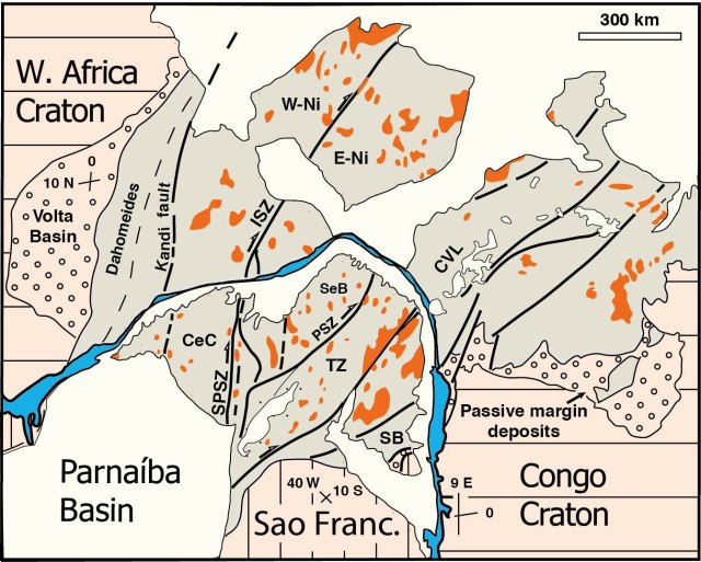
The NE corner of South America (Brazil) and its African counterpart, restored to the pre-Atlantic situation. Modified from Archanjo et al. (Tectonics 2002).

In Brazil the largest shear zones separate blocks of Precambrian basement of somewhat different ages and characteristics, but it is uncertain whether they represent sutures or just intracontinental shear zones formed during the late Neoproterozoic.

Borborema map

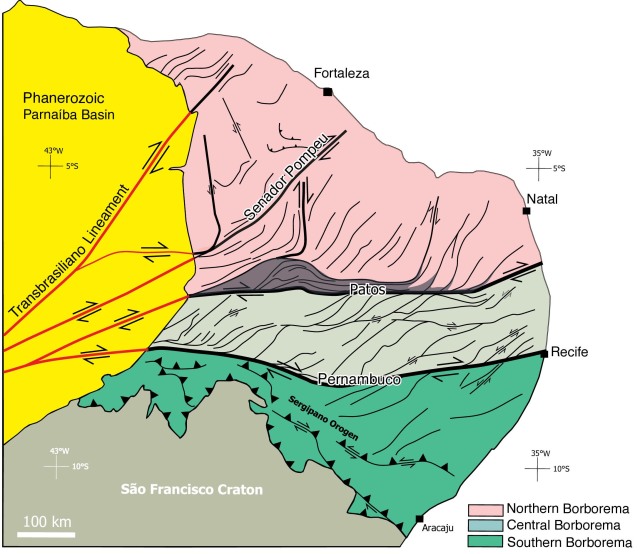
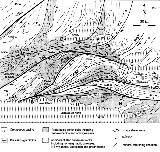
Large-scale shear zone pattern in NE Brazil. Modified from Granade de Araujo et al. (Terra Nova 2014)

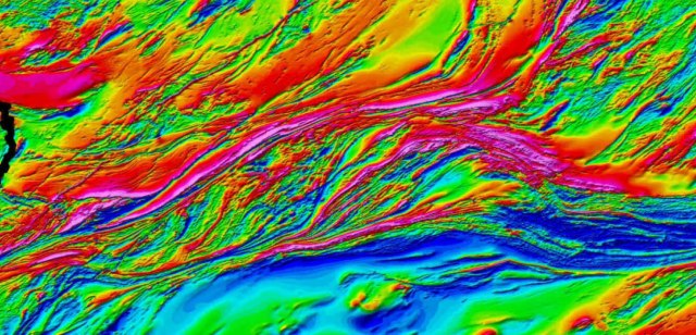
Magnetic maps nicely portray the extraordinary shear zone pattern in this area:

Borborema magnetic

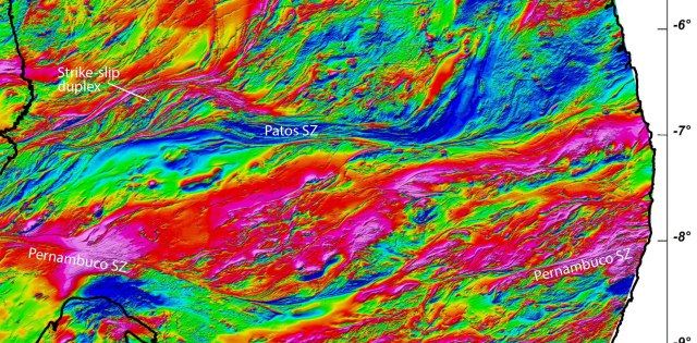
Magnetic image of part of the Borborema province, with the Patos Shear Zone as the main element. Data from the Brazilian Geological Survey. The image is also included in Chapter 1 of the 2nd edition of my structural geology book in Portuguese (Geologia estrutural).

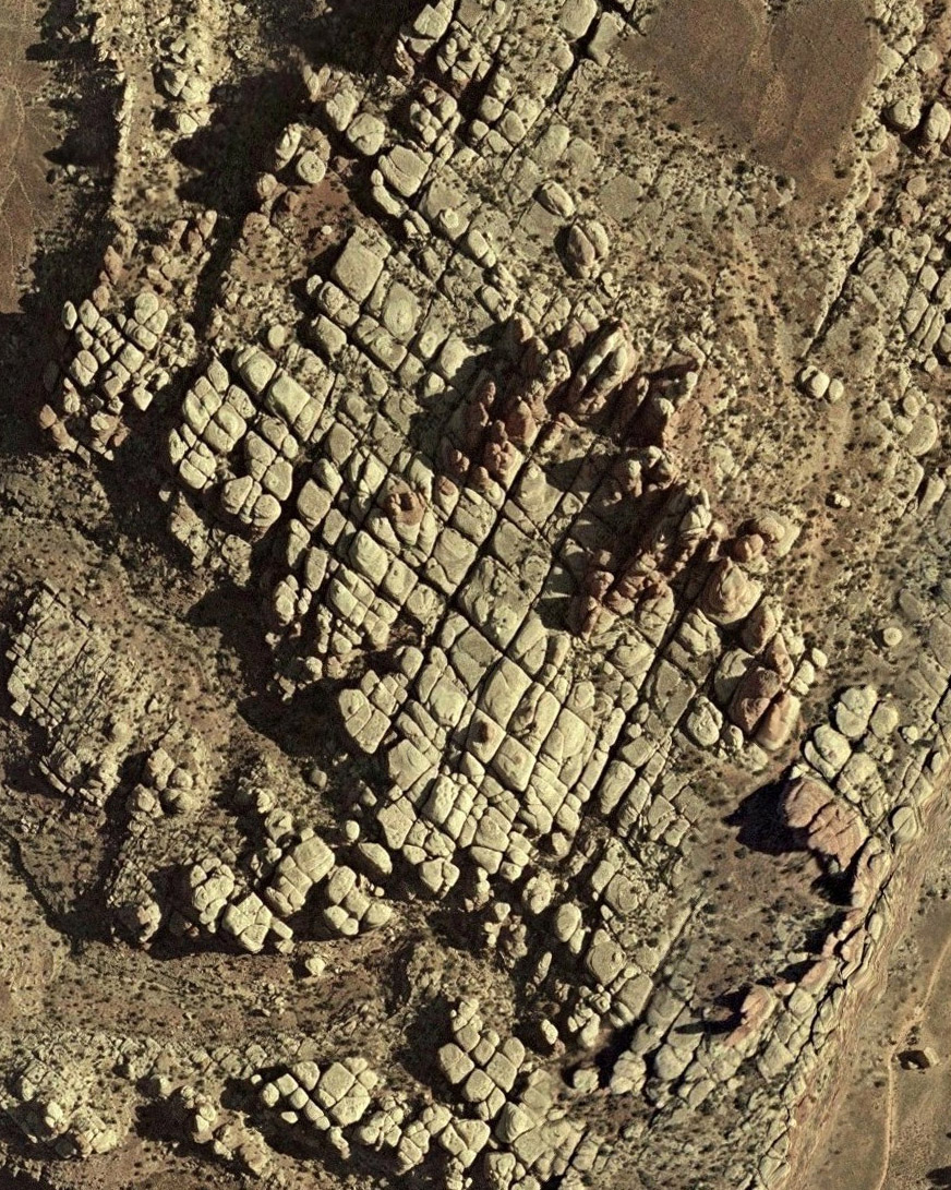
In outcrop, some of the shear zone system formed at high temperatures with melt generation, while other parts formed under lower temperatures. Outcrop pictures shown below.

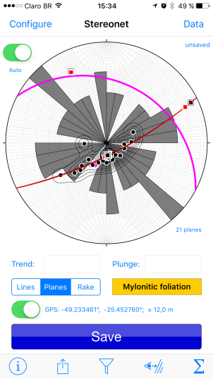
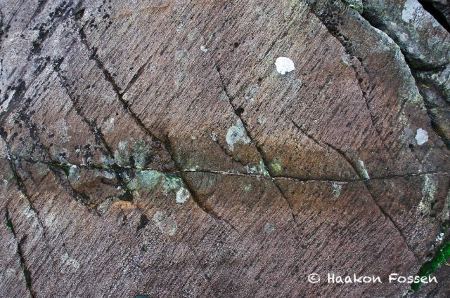
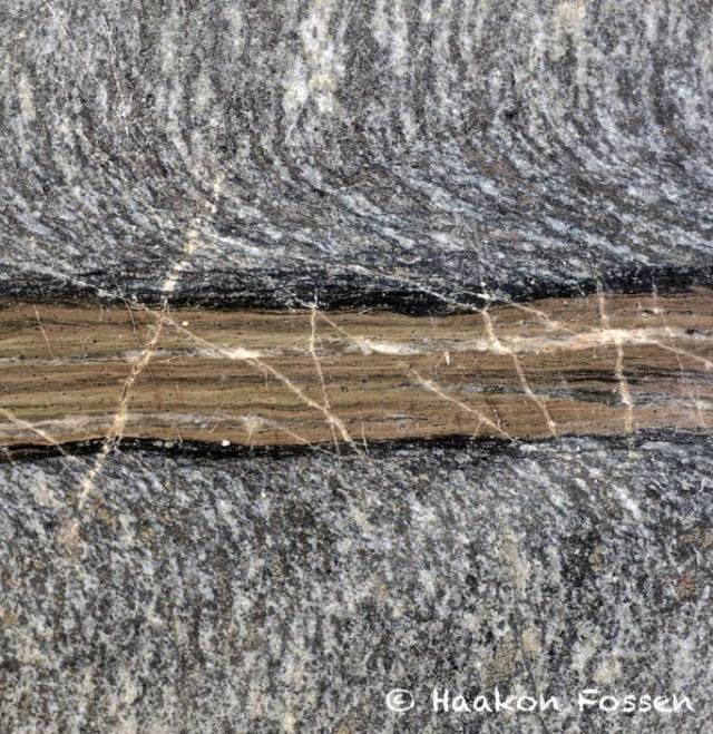
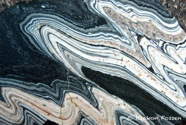
Small-scale structures are abundant, as shown here from mylonites of the S part of the Patos Shear Zone. Click images for higher resolution.

A huge strike-slip duplex is well developed in the western part of the Patos Shear Zone, also showing up nicely on the magnetic map:

PB_MAG

Magnetic map, strike-slip duplex, Patos Shear Zone. Geological Survey of Brazil.

Screen Shot 2018-08-02 at 11.56.08

The strike-slip duplex (Corsini et al. JSG 1996)

In summary, this shear zone system is one of the largest in the world and display the anastomosing patterns of shear zone systems at scales from 1000 km down to that of a thin section. It contains many hidden secrets, and definitely deserves more attention.

Read more about shear zones in:

Fossen, H. & Cavalcante, G. C. G. 2017. Shear zones – A review. Earth-Science Reviews 171, 434-455.


Posted in Uncategorized | 2 Comments

Geologia Estrutural: New edition

The second edition of the Portuguese version of my book was printed a few months ago. Not only does it contain the additions and improvements of the 2nd edition of the English version (see earlier post on this blog), but a number of photos and figures + some boxes have been replaced with Brazilian (and some Portuguese) examples. The book is printed by and available from Oficina de Textos in São Paulo. capa_geo_estrutural

Posted in Uncategorized | Leave a comment

Animations for PowerPoint

A large number of flash animations occur in my e-modules, but they are tricky to get into PowerPoint presentations, which most of us use for presentation and teaching purposes. I ended up making gif-animations of most of them. There is no start/stop option (they loop and play forever), but a start (or stop) functionality can be faked in ppt by copying the first (or last) image and put it on top of the animation. Then use ppt to animate that picture out to reveal the animation. Free

The files are collected in three ppt files (Chapter 1-10, 12-15, and 16-21) that can be downloaded from this website: http://folk.uib.no/nglhe/StructuralGeoBookExcel2ndEd.html

SC rotationOrthorombic fault set for ppt

Posted in Uncategorized | 1 Comment

Stereonet Mobile: New Stereonet app for the iOS

Stereonet Mobile for the iOS (iPhone, iPad) (available from the iOS AppStore) was made by Rick Allmendinger for both collecting data in the field and analyzing data anywhere. Like Rick’s other software, it is a completely free app that is easy to use. It contours data, makes rose diagrams, rotates data, finds angles between planes, has a cool sighting function and works seamlessly with Rick’s desktop Stereonet program. Well worth a try! More at http://www.geo.cornell.edu/…/RWA/prog…/stereonet-mobile.html and https://itunes.apple.com/us/app/stereonet-mobile/id1194772610?mt=8Stereonet Mobile

Posted in Uncategorized | Leave a comment

Shear zone initiation and fractures

a%cc%8adnefj-shear-zone

Subhorizontal fracture (vein) with some ductile bending of the granulitic foliation. Greenish zone (20 cm wide) represents eclogitized granulite. Holsnøy near Bergen, Norwegian Caledonides. This is the early stage of shear zone formation at 50 km depth in these dry rocks. The central vein is usually erased in more advanced stages of shearing.

Ductile shear zones are the results of strain localization in the crust, mostly the middle and lower crust where plastic deformation mechanisms govern. They typically nucleate on preexisting structures such as foliations, veins and fractures, or they can initiate on a new fracture that develops into a plastic shear zone as shearing progresses. Fluid infiltration along these early fractures is important, and softens the rock around the fracture. This development has been described from the Alps, Cap de Creus (Spain), SW Norway and several other places. Here I show an example of a shear zone nucleating on fracture formed under eclogite facies conditions, and a shear zone involving a sheared central epidote vein that guided the strain localization.

jotun-nappe-sheared-vein

Shear zone from the Caledonian Jotun Nappe (S Norway) showing a central ultramylonitic core that represents an early or preexisting vein on which the shear zone nucleated.

Posted in Uncategorized | 2 Comments

Geology photos

In connection with the release of the 2nd edition of Structural Geology, I am posting a series of geology pictures on the facebook page of the book. Here is one of the pictures:

Jotunheimen (Bergverksmuseet Kongsberg)

Folded mylonites from the Norwegian Caledonides

Posted in Uncategorized | 1 Comment

Structural geology, 2nd edition

The second edition of my book is printed and will be shipped out as I write. We wanted to update and add a variety of things; boxes, replacing photos, adding a few illustrations, explaining some things better, etc. The largest single change is a new chapter on joints and veins. Hence the numbering has changed from Chapter 8 (the new chapter). Apart from that, the structure of the book remains the same. Thanks to those of you who sent comments and suggestions for improvements. Feedback is extremely valuable, so please do more of that!CoverPage

The new cover is from the SW coast of Portugal, where Carboniferous turbidites were  involved in thin-skinned folding and thrusting during the Variscan orogeny. A range of beautiful structures are exposed along that coast. A change from the previous cover, which was from the Swiss Alps – another beautiful area to enjoy structures and structural geology.

Let me also mention that I spent time upgrading the online resources, such as additional photos, problem sets, and e-modules. In fact, e-modules are getting a closer link with the chapters in the book, and are recommended to all users of the book. Check resources here:

http://www.cambridge.org/gb/academic/textbooks/fossen2
http://folk.uib.no/nglhe/StructuralGeoBook2ndEd.html

And finally, two very nice endorsements:

“This new edition of Structural Geology has filled in a few gaps in the excellent first edition and the author and publishers are to be congratulated on their efforts to produce a really up-to-date text in a most attractive format.” Professor John Ramsay, ETH Zürich

“This is the best textbook in this field of the past decade. Both the book and the accompanying online resources have been extended with new topics and the animated e-modules are a fantastic extra teaching resource.” Professor Roger Soliva, Université Montpellier II

Posted in Uncategorized | 3 Comments

What thrusting does to porous sandstones (surprisingly little)

The situation: porous sandstone overthrust by Sevier-age thrust sheet. How much did the sandstone suffer? Surprisingly little.

The situation: porous sandstone overthrust by Sevier-age thrust sheet. How much did the sandstone suffer? Surprisingly little.

The place

The place

To many of us, thrust nappes and thrusting are things related to metamorphic rocks or shale-limestone sequences in places such as the Alps, the Caledonides or the Canadian Rockies, while rifts are more commonly associated with porous sandstones and shales. When shale-limestone sequences are shortened, thrusts follow shale beds and ramp up through the more competent limestone units, forming fault-bend folds and fault-propagation folds. This is the style of foreland thrust tectonics that we know from many orogens. But what happens to porous sandstones involved in foreland thrusting?

Porous Aztec Sandstone. The thrust to the overlying Lower Paleozoic Bonanza Group can be seen in the cliff

Porous Aztec Sandstone. The thrust to the overlying Lower Paleozoic Bonanza Group can be seen in the upper part of the cliffs in the background, just above the person’s head. The variations in color in the sandstone are caused by meteoric water dissolving and precipitating iron oxide, a process which is controlled by bedding and shear-enhanced deformation bands alike.

Recent work in Nevada, USA (and also in Provence, France) suggests that the sandstone can survive a lot of overthrusting without much internal strain. It develops deformation bands in high-porosity parts. Specifically it develops compaction bands where porosity is very high, and shear-enhanced compaction bands. Compaction bands are relatively rare and mainly involve band-perpendicular compaction, and are oriented perpendicular to the shortening direction and sigma1. Shear-enhanced deformation bands form two (conjugate) sets as illustrated in the figure (although both sets may not be present in the same outcrop). Hence we develop sets of small-scale structures that constrain the shortening direction very well.

Arrangement of SECB (shear-enhanced compaction bands) and PCB (pure ompaction bands)

Arrangement of SECB (shear-enhanced compaction bands) and PCB (pure compaction bands)

Later during thrusting, as the sandstone is buried and somewhat more lithified (but still porous), cataclastic deformation bands form where grains are more strongly crushed.

Perhaps the most surprising thing that we observe is that these structures are fairly sparsely distributed in the sandstone, and only in a meter-thick zone at the thrust do we see intense deformation of the sandstone. It is amazing (and surprising) to have a several kilometer-thick thrust nappe moving tens of kilometers over a porous sand(stone) without doing more damage (grain crushing, porosity reduction): The sandstone is still highly porous and of good reservoir quality (0.1-1 darcy in large parts of the area). Hence overthrust reservoirs may be of good quality.

Shear-enhanced compaction bands (wide vertical bands) cut by low-angle cataclastic deformation bands.

Shear-enhanced compaction bands (wide vertical bands) cut by low-angle cataclastic deformation bands.

Why is this surprising? Because there is no weak shale or salt layer between the sandstone and the thrust nappe that can take up the shear strain. Just the meter-thick cataclastic zone. It is also difficult to create overpressure in this zone since the sandstone, porous and very thick and probably connected to the surface at the time of thrusting.

Papers:
Fossen, H., Zuluaga, L.F., Ballas, G., Soliva, R. & Rotevatn, A. 2015: Contractional deformation of porous sandstone: insights from the Aztec Sandstone, SE Nevada, USA. Journal of Structural Geology 74, 172-184.

Gregory Ballas, G., Soliva, R., Sizunb, J-P., Fossen, H., Benedicto, A., & Skurtveit, E. 2013: Shear-enhanced compaction bands formed at shallow burial conditions; implications for fluid flow (Provence, France). Journal of Structural Geology 47, 3-15.

Brock, W.G., Engelder, J.T., 1977. Deformation associated with the movement of the Muddy Mountain overthrust in the Buffington window, southeastern Nevada. Geol. Soc. Am. Bull. 88, 1667-1677.

Posted in Uncategorized | Leave a comment

The Caledonian bedrock layer cake in S Norway

Cake model

Cake model

In the South Norway Caledonides – the Himalaya-style mountain chain that formed ca. 420 million years ago when Greenland and Scandinavia smashed into each other – there are three principally different rock units that are stacked on top of each other (top to bottom):

Crystalline thrust nappes (Strong, partly mylonitized)

Phyllite (décollement zone) Lower Paleozoic, very weak and micaceous

Proterozoic basement (Granitoid, Proterozoic structures, very strong)

Basement

Basement

These are theologically very different units: The phyllite-dominated middle layer is very weak compared to the others and acted as a weak décollement on which the overlying Jotun Nappe and other nappes moved. Most of the nappes are thought to have moved several hundred kilometers!

Because the phyllites localized deformation very effectively, the basement was barely deformed during the Caledonian continent-continent collision in many places, at least at the outcrop scale. Proterozoic cross-cutting relations are well preserved!

Phyllite

Phyllite. Shear bands dipping to the right indicate top-to-the-NW (left) sense of shear.

A primary unconformity is locally preserved between the phyllite unit (décollement) and the basement. A conglomerate and weathering arkose can be found in places, showing that the phyllite layer was deposited on the basement during the Cambrian transgression (rise in sea level). Hence the phyllite was mud deposited in a shallow continental ocean.

Conglomerate with phyllitic matrix

Conglomerate with phyllitic matrix

The nappes are also crystalline basement rocks, such as migmatites, granites and gabbros/anorthosite, probably ripped off the basement somewhere to the northwest of the present coastline. But the base of the nappes (base of the orogenic wedge) is strongly mylonitized (sheared), with a strong banding or schistosity. The mylonite zone is typically something like 200 m thick.

Unconformity with basal conglomerate on top of the Proterozoic basement. Phyllite in upper part of the picture

Another view of the unconformity with basal conglomerate on top of the Proterozoic basement. Phyllite in upper part of the picture.

What is perhaps surprising is that the kinematic indicators (asymmetric structures) in both the mylonite zone and the décollement phyllites consistently show top-to-the-NW sense of shear, contrary to the expected collision-related nappe translations. The explanation for this is that the orogenic wedge (nappes) moved back toward the hinterland shortly after the collision finished, suggesting a change from convergent to divergent plate motions shortly before 400 Ma.

Mylonites at the base of the nappe layer (Jotun Nappe)

Mylonites at the base of the nappe layer (Jotun Nappe). Top-to-the-NE (right) sense of shear.

You can read more about the  transgression in “The making of a land  Geology of Norway” (http://www.geologi.no/the-making-of-a-land) and about tectonic aspects in my papers, for example in publications 47 and 86 in my publication list: http://folk.uib.no/nglhe/Publications.html)

Posted in Uncategorized | 3 Comments

Jointing and mechanical layering

Two sets of joints in Permian eolian sandstone, Canyonlands National Park

Two sets of joints in Permian eolian sandstone, Canyonlands National Park. Two joint sets at high angles are quite common in competent beds.

Jointed Cretaceous sandstone layers, Book Cliffs, Utah

Jointed Cretaceous sandstone layers, Book Cliffs, Utah. Note how the distance between joints is larger in the thick layers.

Joints occur pretty much everywhere in rocks exposed at the surface of the Earth. And they can be pretty important, both during construction activities, intrusion of magma and flow of fluids (groundwater, hydrocarbons, CO2, magma). Joints represent conduits of fluids, particularly in the vertical direction, and are made artificially during fracking (hydraulic fracturing) operations.

Jointed silica-rich layers in green shale, Green River Formation, Utah

Jointed silica-rich layers in green shale, Green River Formation, Utah. Note higher joint spacing in thick layer at the top.

Joints form naturally in a variety of settings, but particularly during exhumation due to pressure release and cooling. Thermal contraction is very important, and it is the stiff layers that fracture most easily. Hence we typically see fractured sandstone or limestone layers between non-fractured or less fractured siltstones or shale layers. Layers that develop different joint patterns define what is called mechanical stratigraphy.

Relationship between layer thickness and joint spacing

Relationship between layer thickness and joint spacing, based on field observations.

Typically, stiff layers develop fractures with a characteristic spacing that depends on layer thickness: The thicker the layer, the farther apart the fractures, as shown in some of these pictures.

Posted in Uncategorized | 2 Comments